Orifice Plate MEF
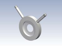
Orifice Plate with Single Pressure Tapping Series MEF

The EMCO Orifice Plate with Single Pressure Tapping Series MEF for Insertion Between Flanges
Principle
EMCO orifice plate are used as primary elements in flow measurement of liquid, gas and steam according to the differential pressure principle. The MEF series are manufactured as a one piece orifice plate orifice carrier assembly with integral corner tapings for installation between flanges as described and specified below.
Construction
- Design and calculation Standards : ISO 5167, ASME MFC-3M, DIN 19205, Shell Flow Meter Engineering Handbook, L. K. Spink, AGA no. 3
- Sizes : DN 50 - 1200, 2" - 42"
- Pressure rating : PN 10 - 400, 150 - 2500 lbs
- Plate thickness : 8 mm
- Vent or drain hole : On request
- Material : Carbon steel P265GH, AISI 316, 16Mo3, 13CrMo4-5, other materials on request.
- Pressure taps : 3/8", 1/2" BSP male, Ø 12 mm, 1/2" NPT
- Tap lengths : 150 mm, others on request.
- Tap location : At least 45 degrees apart. To be stated with order
- Marking : The orifice plate is marked with "+" and"-" and flow direction.
Mounting style :
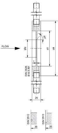
Between flanges with flat or raised face or groove according to DIN 2526, 2513, 2512, or RF according to B 6.5
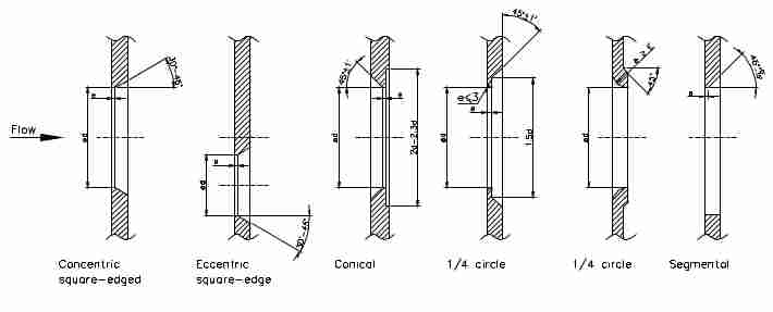
Orifice plate shapes : Square edge concentric, square edge eccentric, conical, 1/4 circle, segment. The plate is bevelled on the down stream side except for 1/4 circle orifice plate.

Technical Data
- Accuracy : /- 0,6 % for β < 0,6 and equal to β for β values above 0,6
- Pressure loss : Depending on β, for β equal to 0,6 : ca. 60 % of the differential pressure measured
- Limits for : Re > 1260 x β2 D according to ISO 5167, Reynolds No 2000 < Re < 108 according to ASME MFC-3M
Accessories : Shut-off valves and condensing chambers for steam flow measurement. Flange assembly complete with bolts, nuts and gaskets.
Sizes
DIN Flanges
| Size | Pipe | PN 10 | PN 16 | PN 25 | PN 40 | PN 64 | PN 100 | d1= | ||||||
|---|---|---|---|---|---|---|---|---|---|---|---|---|---|---|
| DN | OD | D | d4 | D | d4 | D | d4 | D | d4 | D | d4 | D | d4 | D+ |
| 50 | 60.3 | 54.5 | 107 | 54.5 | 107 | 54.5 | 107 | 54.5 | 107 | 54.5 | 113 | 53.9 | 119 | 1 |
| 65 | 76.1 | 70.3 | 127 | 70.3 | 127 | 70.3 | 127 | 70.3 | 127 | 69.7 | 138 | 68.9 | 144 | 1 |
| 80 | 88.9 | 82.5 | 142 | 82.5 | 142 | 82.5 | 142 | 82.5 | 142 | 81.7 | 148 | 80.9 | 154 | 1 |
| 100 | 114.3 | 107.1 | 162 | 107.1 | 162 | 107.1 | 168 | 107.1 | 168 | 106.3 | 174 | 104.3 | 180 | 1 |
| 125 | 133 | 125 | 192 | 125 | 192 | 125 | 194 | 125 | 194 | 124 | 210 | 120.4 | 217 | 2 |
| 125 | 139.7 | 131.7 | 192 | 131.7 | 192 | 131.7 | 194 | 131.7 | 194 | 130.7 | 210 | 127.1 | 217 | 2 |
| 150 | 159 | 150 | 218 | 150 | 218 | 150 | 224 | 150 | 224 | 147.8 | 247 | 144.8 | 257 | 2 |
| 150 | 168.3 | 159.3 | 218 | 159.3 | 218 | 159.3 | 224 | 159.3 | 224 | 157.1 | 247 | 154.1 | 257 | 2 |
| 175 | 193.7 | 182.9 | 248 | 182.5 | 254 | 182.5 | 265 | 181.1 | 277 | 176.1 | 287 | 2 | ||
| 200 | 219.1 | 207.3 | 273 | 207.3 | 273 | 206.5 | 284 | 206.5 | 290 | 204.9 | 309 | 199.1 | 324 | 2 |
| 250 | 273 | 260.4 | 328 | 260.4 | 329 | 258.8 | 340 | 258.8 | 352 | 255.4 | 364 | 248 | 391 | 2 |
| 300 | 323.9 | 309.7 | 378 | 309.7 | 384 | 307.9 | 400 | 307.9 | 417 | 301.9 | 424 | 295.5 | 458 | 2 |
| 350 | 355.6 | 341.4 | 438 | 339.6 | 444 | 339.6 | 457 | 338 | 474 | 330.6 | 486 | 323.6 | 512 | 2 |
| 350 | 368 | 353.8 | 438 | 353.8 | 444 | 352 | 457 | 350.4 | 474 | 343 | 486 | 336 | 512 | 2 |
| 400 | 406.4 | 392.2 | 489 | 390.4 | 495 | 388.8 | 514 | 384.4 | 546 | 378 | 543 | 2 | ||
| 400 | 419 | 404.8 | 489 | 403 | 495 | 401.4 | 514 | 397 | 546 | 390.6 | 543 | 2 | ||
| 500 | 508 | 493.8 | 594 | 492.9 | 617 | 488 | 624 | 479.6 | 628 | 4 | ||||
| 600 | 610 | 595.8 | 695 | 592.4 | 734 | 588 | 731 | 4 | ||||||
| 700 | 711 | 695 | 810 | 693.4 | 804 | 686 | 833 | 4 | ||||||
| 800 | 813 | 797 | 917 | 793 | 911 | 784.6 | 942 | 4 | ||||||
| 900 | 914 | 896 | 1017 | 894 | 1011 | 882 | 1042 | 4 |
Overall Dimensions

All dimensions in mm
D : Inner pipe diameter
d4 : Outer diameter of carrier rings when mounted between flanges with facing according to DIN 2526.
d1 : Inner diameter plate holder. When mounted between flanges with facing according to DIN 2512 and 2513, the inner diameter is D + 1.2 mm.
Works with:-
Differential pressure transmitters:-IDP10; IDP15; IDP25; IDP31; IDP50
And all our Absolute Pressure and Gauge Pressure transmitters, Temperature sensors and mass flow computers.
MultiVariable Transmitters :- IMV25, IMV30
If you require further information on this product or would like a quotation, please contact dp-flow on:
email: sales@dp-flow.co.uk
sales +44(0)1608 544222
Supplied by DP-Flow